Introduction
Engineering drawing forms the backbone of modern engineering and manufacturing, serving as a universal language through which complex ideas about the shape, size, and features of mechanical components, structural elements, and systems are conveyed with clarity and precision. Central to this visual language are various types of lines, each carrying specific meaning, purpose, and function. These lines adhere to strict standards, ensuring that drawings produced in diverse industries and regions maintain consistency and are universally understood by engineers, architects, manufacturers, and construction professionals alike.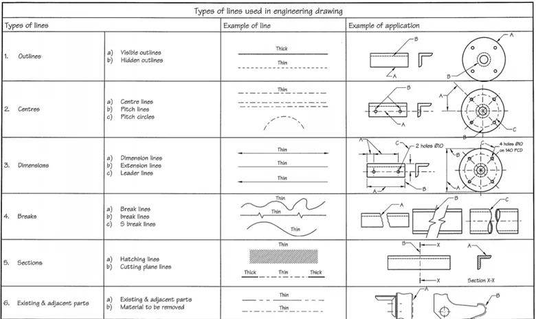
The importance of precise line use cannot be overstated; it influences the clarity, accuracy, and ultimately the success of a project. Misinterpretation due to improper line conventions can lead to costly errors in manufacturing, construction, or assembly. As the foundation of technical communication, the understanding and application of different line types are pivotal skills for professionals engaged in technical drawing, design, and engineering analysis.
This comprehensive exploration, hosted on aims to serve as an authoritative resource through the Free Source Library platform (freesourcelibrary.com), delves into all significant categories of lines used in engineering drawings. We will discuss each line type’s purpose, conventions, standardization, and representation, illustrating their necessity in conveying complex information effectively. Moreover, we will examine the standards governing these lines, their application across various disciplines, and how mastery of these conventions ensures seamless communication and manufacturing precision.
The Role of Standardized Lines in Engineering Drawing
Before delving into specific line types, it is vital to understand the overarching significance of standardization in engineering graphics. The use of uniform line types ensures that drawings can be universally interpreted regardless of geographic location or industry specifics. Standards such as ISO (International Organization for Standardization) 128 and ANSI Y14.2 govern the line types and their characteristics. These standards dictate not only the appearance of each line type but also their thickness, spacing, and application, fostering clarity, reducing ambiguity, and streamlining communication across multidisciplinary teams and international borders.
Adherence to these standards allows for clear differentiation between the various features depicted in a drawing. The different line types symbolize visible edges, hidden features, axes of symmetry, measurement boundaries, and auxiliary construction lines, each visually distinct through specific stroke patterns, thicknesses, and positioning conventions.
The Core Line Types in Engineering Drawing
1. Visible or Object Lines
Visible lines, also called object lines, form the fundamental outline of components and structures within a drawing. They are solid, continuous lines thick enough (commonly 0.6 mm) to stand out clearly against other line types. Their primary role is to delineate the external contours and all visible edges of the object or component from the viewer’s perspective.
These lines are essential in defining the overall shape and form, offering a clear visual guide to understanding the physical boundaries. In complex assemblies, they also serve to highlight the main features, such as the edges of a gear, the outline of a bracket, or the external face of a structural beam. The thickness of visible lines ensures their dominance in the drawing, as they are the primary carriers of the visible geometry information.
2. Hidden Lines
Hidden lines represent features of the object that are obscured from the viewer’s perspective, such as internal cavities, holes, or edges concealed behind other components. They are drawn as short, evenly spaced dashes, with typical dash lengths around 2-3 mm and gaps of about 1 mm, with a thinner stroke (around 0.35 mm) than visible lines.
These lines serve as a vital communication tool for revealing internal features without cluttering the drawings. For example, in a mechanical part with drilled holes or internal channels, hidden lines mark those features clearly, enabling engineers and fabricators to understand hidden details essential for manufacturing and assembly.
3. Center Lines
Center lines are fundamentalwhen dealing with symmetrical parts, circular features, or axes of rotation. They delineate the center of circles, arcs, and symmetrical components, aiding in positioning and alignment. The standard style involves alternating long (about 10-20 mm) and short dashes (around 2-3 mm), with a line thickness of approximately 0.35 mm.
Exact placement of center lines facilitates the accurate location of features during manufacturing or assembly processes, assists in establishing axes for machining, and serves as reference points during measurement and inspection. Their distinct pattern ensures they are not confused with other dashed lines, maintaining focus on the pivotal symmetry or rotation axis being depicted.
4. Dimension Lines
The primary purpose of dimension lines is to communicate precise measurements necessary for manufacturing and verification. They consist of a thin line (about 0.25 mm) with arrowheads or tick marks at each end, pointing to the exact points being measured. The measurement data are placed parallel or above the line for easy reading.
Dimension lines are fundamental to technical drawings because they quantify the size of features with high clarity. For complex geometries, they define distances, diameters, radii, or angles, translating pictorial geometry into quantifiable data essential for machining, fabrication, or construction.
5. Extension Lines
Extension lines are auxiliary lines that extend from the edges of an object to connect with the dimension lines. They do not touch the object directly but start a short distance away—typically about 1-2 mm—and extend to meet the dimension line. These thin lines (around 0.25 mm) foster clarity by indicating the points of measurement without cluttering the drawing.
These lines provide spatial separation from the object edges and prevent misinterpretation, particularly when multiple dimensions are close together. Proper extension line placement is crucial to maintain diagram legibility and measurement accuracy.
6. Leader Lines
Leader lines are thin, angled lines used to connect notes, symbols, or specific features on a drawing. They typically terminate with an arrowhead or dot pointing directly at the feature or detail being referenced. Leader lines are usually drawn at an angle (around 30-45 degrees) and are essential for annotating features that cannot be directly labeled within the drawing, such as specifying material or manufacturing notes.
Effective use of leader lines ensures that annotations and notes do not obscure the main drawing features, facilitating quick understanding and reducing ambiguity. They serve as an essential communication link between the drawing and supplementary information such as notes, tolerances, or specifications.
7. Section Lines
Section lines, or crosshatch lines, are used within sectional views to highlight areas that are cut through. These lines are typically drawn at a 45-degree angle and are evenly spaced, often about 1-2 mm apart. They symbolize the cut surfaces in the sectional view, giving a visual cue that part of the object has been sliced to reveal internal features.
In multi-layered or complex assemblies, sectional lines clarify internal configurations, such as cavities, holes, or internal reinforcements. The density and patterning of these lines vary depending on the material being represented; for example, steel and aluminum may have different hatch patterns to distinguish materials visually.
8. Break Lines
Break lines are used to truncate or omit parts of an object to conserve space or focus on specific features. Two types are prevalent:
- Long break lines: Represented as freehand zigzags, these are used to indicate a break in long, uniform, or repetitive features like shafts or beams.
- Short break lines: Wavy or jagged solid lines representing partial sections or interrupted views.
Both types are drawn as thin lines (about 0.25 mm) and aid in emphasizing critical sections or reducing unnecessary detail, making large or repetitive features manageable within the drawing space.
9. Phantom Lines
Phantom or reference lines are thin lines consisting of long dashes alternating with two short dashes. These lines often illustrate paths of motion, alternate positions, or interchanged components. They are typically about 0.25 mm in thickness and are used for schematic clarity rather than precise measurement.
Phantom lines aid in depicting relationships between moving parts, indicating operational mechanisms or the possible repositioning of parts during assembly or function.
10. Cutting Plane Lines
Cutting plane lines are used to show where an object is sliced to generate a sectional view. These lines are thick (about 0.6 mm), drawn as alternating long and short dashes, with arrowheads indicating the viewing direction. They precisely delineate the boundary of the sectioned area, providing clarity on the sectional view’s scope.
The proper placement of cutting plane lines enables clear identification of the object’s internal features and facilitates the straightforward interpretation of sectional graphics.
11. Chain Lines
Chain lines consist of evenly spaced long and short dashes, similar but slightly thicker (around 0.35 mm) than phantom lines. They are used primarily to indicate the positions of repeated details, such as bolt holes, gear teeth, or positional references within an assembly.
Drawing these lines accurately ensures that repeated or positional features are consistent and properly aligned across views or different drawings of the same component.
12. Guide (Construction) Lines
Guide lines are auxiliary, very light, thin lines often drawn freehand during the sketching stage of drawing. Typically around 0.18 mm in thickness, they help lay out the main features, establish proportions, and align different elements within the drawing. They are ultimately erased or hidden behind final lines, serving purely as construction aids.
Mastery of construction lines allows draftsmen and engineers to efficiently develop complex figures with precise alignment, ensuring a clean and professional presentation of the drawing.
13. Border Lines
Border lines define the limits of the drawing area. They are the thickest lines used in an engineering drawing, generally around 0.8 mm, creating a clear boundary frame for the entire sheet. This framing helps contain and organize the drawing, providing a professional appearance and facilitating proper scaling and presentation.
Standardization and Conventions in Line Use
The adherence to standards such as ISO 128 and ANSI Y14.2 enforces uniformity, ensuring that all drawings across industries and regions communicate consistently. These standards specify the line types, their thicknesses, patterns, and usage contexts, fostering a universal understanding crucial for manufacturing precision and collaborative engineering efforts.
For example, the standard thickness for visible outline lines (0.6 mm) ensures they are prominent yet not overwhelming, while hidden lines are thinner (around 0.35 mm) to subtly indicate internal features. The dash patterns for hidden and center lines prevent visual confusion, and the use of thick lines for cutting planes highlights the importance of sectional views.
Applications Across Industries
The wide adoption of standardized line conventions is vital across various industries, including:
- Mechanical Engineering: Precise depiction of components, assemblies, and machining features.
- Civil and Structural Engineering: Detailed representations of buildings, bridges, and infrastructure components where internal details and sectional views are critical.
- Architecture: Floor plans, sections, and elevations rely heavily on varied line types for clarity and detail.
- Manufacturing and Fabrication: The accurate translation of drawings into physical parts depends on clear depiction of features, clear measurements, and reference points established through line conventions.
The Significance of Accurate Line Use in Modern Engineering
In the era of Computer-Aided Design (CAD), the importance of understanding line conventions remains undiminished. CAD systems automate drawing generation but still rely fundamentally on the correct configuration and interpretation of line types. Mastery of these conventions ensures that digital files are not only accurately generated but also correctly interpreted during manufacturing, inspection, or modification processes.
The correct application of line types supports Quality Control and inspection standards, facilitating the creation of precise tolerances and measurements, which are critical for ensuring the functionality, safety, and longevity of manufactured components and structures.
Educational and Professional Development
For students, apprentices, and professionals in engineering, architecture, drafting, and related fields, learning to accurately apply and interpret various line types is a foundational skill. It enables effective communication of complex ideas and is a core competency for proficiency in technical drawing and design software.
Many professional certification programs, such as CAD training courses and engineering licensure exams, emphasize detailed knowledge of line conventions and standards to ensure engineers and draftsmen can produce and interpret detailed, accurate drawings consistently.
Conclusion
The elaborate system of lines used in engineering drawing serves as a comprehensive, standardized language imperative for precise communication across diverse fields and industries. Recognizing and applying these lines with fidelity assures that design intent is conveyed unambiguously, facilitating manufacturing, construction, and maintenance processes worldwide. Adherence to established conventions, alongside continuous professional development, ensures the integrity, clarity, and effectiveness of engineering documentation—cornerstones of modern technological progress.
By understanding the different types of lines—what they represent, how they are drawn, and their specific conventions—engineers and draftsmen can produce drawings that transcend language barriers, reduce errors, and accelerate innovation, aligning with the mission of ideas shared on platforms like the Free Source Library (freesourcelibrary.com).
References
- ISO 128-20:2001 (Technical drawings — General principles of presentation)
- ANSI Y14.2-2020 (Line Conventions and Dimensioning)