
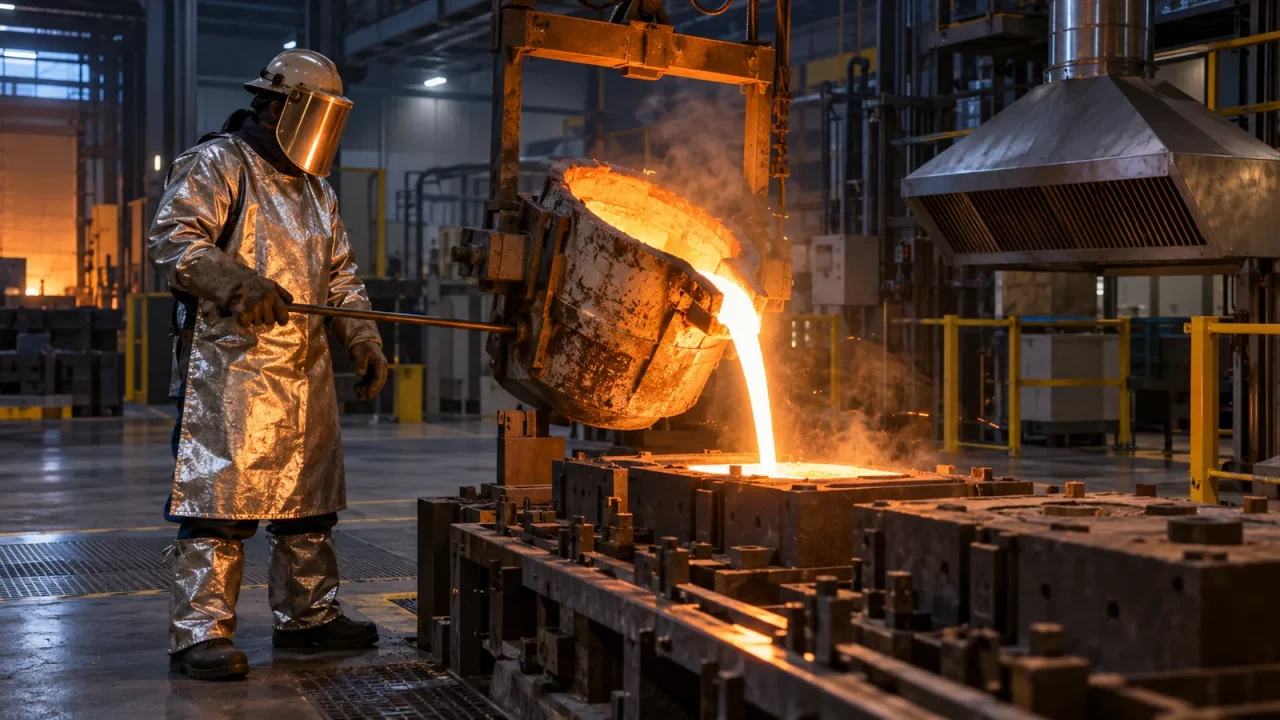
Sand casting is one of the oldest and most adaptable ways to shape metal. A pattern creates a cavity in compacted sand, molten metal fills that cavity, and the mold is broken to release the part. The concept is simple enough to summarize in one sentence, yet reliable castings require control of geometry, sand properties, temperature, gas, metal flow, solidification, and worker safety.
This introduction follows the sand casting process from design through inspection. It explains why patterns include extra features, how runners and risers work, what causes common defects, where the method makes economic sense, and why molten-metal work belongs in a properly designed foundry—not an improvised home setup.
At a glance
- Sand casting works with a wide range of metals and part sizes.
- The mold is usually expendable, while the pattern can be reused.
- Good gating delivers clean metal calmly; risers feed shrinkage during solidification.
- Surface finish and dimensional accuracy are generally lower than investment casting or machining.
- Silica dust, fumes, heat, noise, lifting, and molten metal create serious hazards requiring engineering controls and training.
Where sand casting fits
The process is used for pump housings, engine components, machine bases, cookware, art, valves, agricultural parts, and enormous industrial castings. It handles aluminum, bronze, brass, cast iron, steel, and other alloys, provided the mold system and process are designed for the metal’s pouring temperature and behavior.
Sand casting is attractive for prototypes, replacement parts, low-to-medium production, and shapes too large or uneconomical for a permanent die. Tooling can be less expensive than die casting, but each mold usually must be made again. High-volume lines automate molding and pouring; jobbing foundries may make highly varied parts in smaller quantities.
The main elements of a sand mold
A two-part flask supports the sand. The upper half is the cope, and the lower is the drag. The dividing surface is the parting line. A pattern forms the casting cavity. A sprue carries metal downward, runners distribute it horizontally, and gates connect runners to the cavity. Risers hold additional liquid metal that feeds the casting as it contracts.
Cores create internal passages or undercuts that a simple split pattern cannot form. Core prints on the pattern locate and support them. Vents allow gases to escape. Chills—pieces of conductive material placed strategically—can accelerate local solidification and control feeding.
Pattern design: the casting starts before the mold
A pattern is not always an exact copy of the finished part. Designers account for:
- Shrinkage allowance: metal contracts as it cools, with the amount depending on alloy and geometry.
- Machining allowance: extra material remains on surfaces that will be cut to final tolerance.
- Draft: slight taper helps remove the pattern without tearing the mold.
- Fillets: rounded internal corners reduce stress concentration and improve flow.
- Distortion allowance: some shapes warp predictably and may need compensation.
- Parting-line strategy: a good split simplifies molding, core placement, and cleanup.
Patterns may be wood, plastic, metal, foam, or additively manufactured material. Wood is economical for lower quantities; metal withstands automated repetition; 3D printing enables rapid iteration and complex master patterns.
Molding sand and binder systems
Green sand is not green in color. It is a moist mixture commonly containing silica sand, clay such as bentonite, water, and additives. It is reusable and dominant in many production foundries. Its properties—strength, permeability, compactability, and moisture—must be controlled.
Chemically bonded sand uses resin or other binder systems and can provide high mold strength for large or complex castings. Shell molding coats heated patterns with resin-bonded sand to form a thin shell with improved finish. Lost-foam casting surrounds an expendable foam pattern with unbonded sand; pouring metal vaporizes the pattern.
The best system depends on alloy, size, finish, production volume, reclamation equipment, emissions controls, and cost. Binder choice also affects gas generation and worker exposure.
The sand casting process step by step
1. Engineering and simulation
The team defines alloy, mechanical requirements, tolerances, machining stock, parting line, cores, gating, and feeding. Solidification and flow simulation can identify hot spots, turbulence, air entrainment, and shrinkage risk before tooling is built.
2. Pattern and core tooling
The pattern and core boxes are manufactured and checked. Identification marks, orientation, and allowances must match the drawing. A defective pattern reproduces its error in every mold.
3. Mold preparation
The drag is placed around the pattern, filled with conditioned sand, and compacted. It is turned, the cope is positioned, and sprue and riser features are formed. After compacting the cope, the halves separate and the pattern is withdrawn carefully.
4. Core placement and mold closing
Cores are positioned in their prints, loose sand is removed, and coatings may be applied to improve surface quality. The cope and drag are aligned and clamped or weighted to resist metallostatic force.
5. Melting and treatment
Metal is melted in equipment suited to the alloy. Chemistry, temperature, dissolved gas, and inclusions may be measured or treated. Aluminum alloys may require degassing; iron treatment varies by grade. Excess temperature can increase oxidation, gas pickup, mold reaction, and energy use, while insufficient temperature causes misruns.
6. Pouring
Metal enters the sprue at a controlled rate. Gating should minimize splashing, aspiration, turbulence, and erosion. The pouring basin must stay adequately full so the system draws metal rather than air.
7. Solidification and cooling
The casting begins freezing at surfaces in contact with the mold. Designers aim for directional solidification toward a riser that remains liquid long enough to feed contraction. Cooling time balances productivity against the risk of distortion, hot tearing, or unsafe shakeout.
8. Shakeout and finishing
The mold is broken, and sand is separated for reclamation or disposal. Gates and risers are removed. Blasting, grinding, heat treatment, straightening, machining, and coating may follow.
9. Inspection
Visual and dimensional checks are basic. Dye penetrant or magnetic-particle testing detects surface-breaking flaws in suitable alloys. Radiography or ultrasonic testing can reveal internal discontinuities. Mechanical tests and chemical analysis verify material performance.
Gating and risers: control the liquid path
A gating system is not plumbing added after part design. Sudden direction changes, sharp corners, an unfilled sprue, or gates aimed at fragile sand can entrain air and oxide films or erode the mold. Filters and ceramic foam may capture inclusions and calm flow, but they do not rescue a fundamentally poor layout.
Risers must contain enough hot metal and connect to the area they feed. A riser that freezes before the casting cannot compensate for contraction. Exothermic or insulating sleeves can keep risers liquid longer while reducing the amount of metal later cut off and remelted.
Common defects and what they suggest
| Defect | Appearance | Common contributing factors |
|---|---|---|
| Gas porosity | Rounded voids | Moisture, dissolved gas, poor venting, turbulent flow, binder gas |
| Shrinkage porosity | Irregular cavities in hot spots | Inadequate feeding, poor riser placement, isolated heavy sections |
| Misrun | Incomplete filling | Low temperature, slow flow, thin sections, inadequate gating |
| Cold shut | Seam where streams failed to fuse | Premature cooling, oxide films, divided flow |
| Sand inclusion | Sand trapped in metal | Mold erosion, weak sand, poor cleaning, turbulent impingement |
| Hot tear | Irregular crack during cooling | Restricted contraction, abrupt section changes, alloy susceptibility |
| Mismatch | Offset at parting line | Poor flask alignment, worn pins, inadequate clamping |
A defect name is the start of investigation, not a root cause. Teams use sectioning, microscopy, process records, simulation, and controlled trials to distinguish similar-looking problems.
Design rules that improve castability
Keep wall thickness as uniform as function allows, transition gradually between sections, and use generous fillets. Avoid isolated heavy bosses that create hot spots. Place machining surfaces where tooling and cutters can reach them. Reduce unnecessary cores: each core adds cost, tolerance stack-up, gas, handling, and potential shift.
Tolerances should match the process. Demanding machined precision directly from a rough casting raises cost and scrap. Define which surfaces truly control function and leave cosmetic areas appropriately flexible.
Foundry safety is an engineering system
OSHA identifies foundry hazards including silica and other dust, lead and metal exposures, gases, heat stress, noise, forceful material handling, repetitive work, and awkward posture. Molten metal adds catastrophic burn and explosion risk. Water contacting molten metal can flash to steam and violently eject metal.
Professional controls include enclosed and ventilated sand handling, local exhaust, dust collection, dry charge materials and tools, furnace maintenance, guarded machinery, rated lifting equipment, exclusion zones, spill containment, written procedures, training, and emergency planning. Personal protective equipment is the last layer, not a replacement for engineering controls.
Respirable crystalline silica can cause silicosis, lung cancer, chronic obstructive pulmonary disease, and kidney disease. Dry sweeping or compressed-air cleaning can launch dust into workers’ breathing zones. Exposure assessment and compliant housekeeping are essential.
This article is not a do-it-yourself pouring guide. Do not melt or pour metal in a kitchen, living space, ordinary garage, or around bystanders. Internet videos cannot validate ventilation, refractory condition, moisture control, protective clothing, or emergency capacity.
Cost and sustainability
Economics include pattern and core tooling, molding labor, metal yield, melting energy, scrap, finishing, machining, inspection, and lead time. A cheap pattern that creates excess flash or a low-yield gating system can cost more across production than better upfront engineering.
Many foundries reclaim sand mechanically or thermally, return gates and risers to the melt where metallurgy permits, and improve yield through simulation. Energy efficiency, binder emissions, dust capture, responsible slag handling, and alloy traceability all affect environmental performance. Reuse is not unlimited: sand properties and contaminants must be monitored.
Process records and traceability
A foundry cannot improve what it does not record. Useful records link each casting or heat to alloy chemistry, charge materials, melt and pour temperatures, treatment time, mold and core batches, sand tests, operator, shakeout time, heat treatment, inspection results, and nonconformance disposition. Trends can reveal a drifting moisture controller, worn pattern equipment, contaminated return metal, or a defect concentrated on one shift.
Traceability should be proportional to risk. A decorative part and a pressure-retaining or safety-critical casting do not require the same documentation, qualification, or nondestructive examination. Customer drawings, applicable standards, and quality plans define acceptance; a visually clean surface alone cannot certify internal integrity or material properties.
Frequently asked questions
Why use sand if the mold is destroyed?
Sand is inexpensive, refractory, shapeable, scalable, and often reclaimable. Expendable molds enable geometry and size that a permanent metal die may not accommodate economically.
Is sand casting accurate?
It can produce controlled dimensions, but finish and tolerance are generally looser than die casting, investment casting, or machining. Critical surfaces are commonly machined.
What is green sand?
Moist clay-bonded molding sand. “Green” refers to its damp, uncured state, not its color or environmental certification.
Can 3D printing replace patterns?
It can produce patterns, core boxes, sand molds, or expendable forms, especially for prototypes and complex low-volume work. Cost, material compatibility, accuracy, and production rate determine whether it is appropriate.
Bottom line
Sand casting succeeds when design, molding material, metal treatment, flow, feeding, cooling, finishing, and inspection operate as one controlled system. Its flexibility is enormous, but so are the consequences of poor process control. Learn the principles through simulation, laboratories, and supervised industrial training; leave molten-metal work to facilities built to manage it.
Sources
- U.S. OSHA: Ergonomics for the Prevention of Musculoskeletal Disorders—Foundries
- U.S. OSHA: Respirable Crystalline Silica
- NIOSH: Silica and worker health
Evidence reviewed: October 16, 2026.